3-20dB Power Tapper 350-5925 MHz
Product Model : T0360-XX-OMH
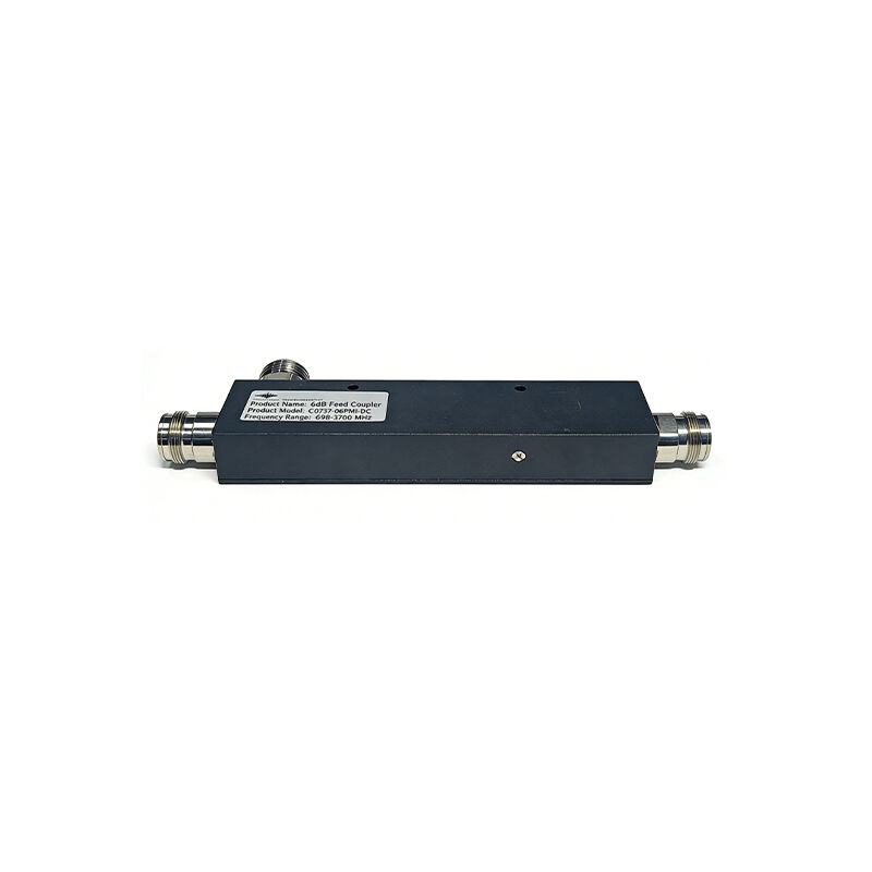
Tappers, also known as signal samplers, work on a principle highly similar to that of directional couplers. The device can extract all signals regardless of the direction of signal transmission, Its core function is to accurately draw a portion of power from the main transmission line and distribute it to multiple output ports. While ensuring low-loss transmission of the main signal, it realizes equal or proportional signal distribution with stable phase consistency and impedance matching. Tappers are widely used in Distributed Antenna Systems (DAS), with two interface specifications available: Type N and 4.3-10 mini DIN type.
Product Description
♦ Wide Frequency Band 350-5925MHz
♦ 2G/3G/4G/5G/LTE Coverage
♦ Low Passive Inter-modulation
♦ Low VSWR & Insertion Loss
♦ Indoor or Outdoor application
♦ Widely used for In-building Solutions

- Specifications
- Outline Drawing
- Applications
- Recommended Products
Specifications
| Product Model | FCT0360-xx-OMH* FCT0360-xx-ONH* | |
| Frequency range | 350 - 960, 1710 - 5925 MHz | |
| Dissipative Loss | ≤ 0.1 dB (main line) | |
| Inter-modulation IM3 | ≤-160 dBc (2 x 43 dBm) | |
| Power capacity | avg. 500 W, peak 3 kW | |
| Impedance | 50 Ω | |
| RF Connector Type | 4.3-10 Female or N-Female | |
| Net Weight | ≤0.4 kg | |
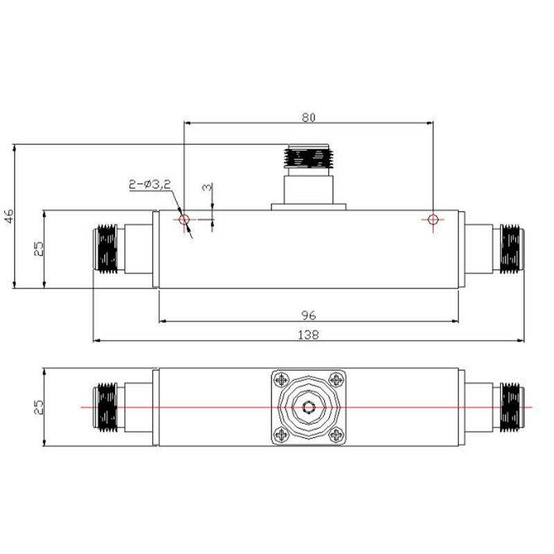
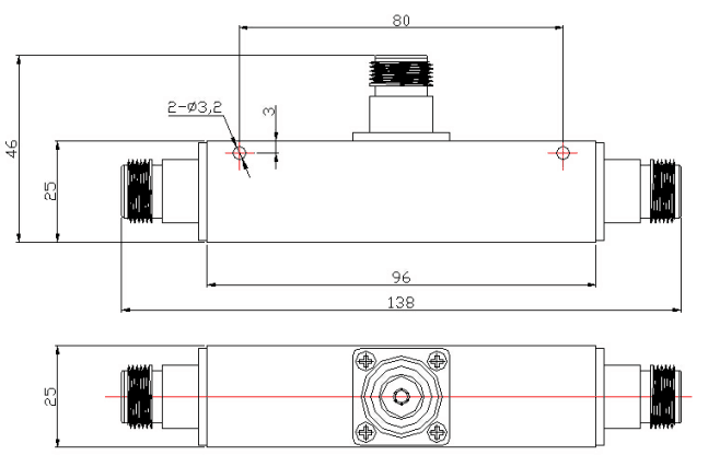
| Dimension(exclude connectors) | 96 x 25 x 25 mm /3.78x0.98x0.98 inch | |
| Operating temperature -35℃ to +65℃ | ||
| Relative humidity | 0 - 95 % | |
| Ingress protection | IP65 | |
Product Selection:4.3-10 Female or N-Female
| Part No | Model | Main/Branch Output Split, dB | Branch Flatness to Input Level (Include Loss), dB | Max Input VSWRΔ | ||||||
| 350-380 | 380-520 | 698-960 | 1710-2700 | 3300-4500 | 4900-5925 | 698-2700 | 350-5925 | |||
| S11H22001 | 3dB | -1.8/-4.8 | +0/-1.3 | +0.3/-1.0 | ±0.5 | ±0.5 | +0/-1.5 | ± 0.5 | 1.3 | 1.5 |
| S11H22002 | 5dB | -1.3/-6.1 | +0/-1.3 | +0.3/-0.8 | ±0.5 | ±0.5 | +0/-1.5 | ± 0.5 | 1.3 | 1.5 |
| S11H22003 | 6dB | -1.0/-7.0 | +0/-1.3 | +0.3/-0.8 | ±0.5 | ±0.5 | +0/-1.5 | ± 0.5 | 1.3 | 1.5 |
| S11H22005 | 8dB | -0.7/-8.6 | +0/-1.3 | +0.3/-0.5 | ±0.5 | ±0.5 | +0/-1.5 | ± 0.5 | 1.3 | 1.5 |
| S11H22006 | 10dB | -0.4/-10.4 | +0/-1.3 | +0.3/-0.5 | ±0.5 | ±0.5 | +0/-1.5 | ± 0.6 | 1.3 | 1.5 |
| S11H22007 | 13dB | -0.2/-13.2 | ±1.0 | ±0.6 | ±0.6 | ±0.6 | +0/-1.5 | ± 0.6 | 1.3 | 1.5 |
| S11H22008 | 15dB | -0.1/-15.1 | ±1.0 | ±0.7 | ±0.7 | ±0.7 | +0/-1.5 | ± 1.0 | 1.3 | 1.5 |
| S11H22009 | 20dB | -0.1/-20.1 | ±1.0 | ±1.0 | ±1.0 | ±0.7 | +2/-0 | +4/-0 | 1.3 | 1.5 |
* xx – Coupling value, 05 – 5dB, 10 – 10dB, 20 – 20dB
Δ–VSWR defines only the effective frequency range
Outline Drawing
Applications
Product Description of Tappers (Signal Tappers)
Tappers, also known as signal samplers, work on a principle highly similar to that of directional couplers. The device can extract all signals regardless of the direction of signal transmission, Its core function is to accurately draw a portion of power from the main transmission line and distribute it to multiple output ports. While ensuring low-loss transmission of the main signal, it realizes equal or proportional signal distribution with stable phase consistency and impedance matching. Tappers are widely used in Distributed Antenna Systems (DAS), with two interface specifications available: Type N and 4.3-10 mini DIN type.
Differences between Tappers and Directional Couplers
1. Differences in Coupling and Directivity
Tappers mostly adopt capacitive coupling and are non-directional bidirectional devices. They provide consistent coupling for forward and reverse signals and do not have echo path isolation capability. Directional couplers sample signals flowing in one direction only. These directional couplers include parallel line couplers and loop couplers. Directional couplers provide flat coupling, high directivity and low VSWR. Directivity is approximately 20 dB for printed couplers, 25 dB or more for air dielectric couplers. Units can be supplied with coupling ranging from 3 dB to 50 dB.
2. Differences in Port Configuration and Functional Focus
Tappers are generally three-port devices. Their core function is to extract a small portion of signals from the main transmission line in non-uniform proportions (ranging from 2:1 to 1000:1). Tappers are only used for signal combining in a few scenarios and are more commonly applied for test signal injection. Directional couplers are mostly four-port devices. In addition to signal sampling, they can also realize signal distribution and combining, serving as versatile devices with both sampling and power combining functions.
3. Differences in Performance Parameters
Tappers have a wider operating frequency band, covering 350MHz–5925MHz, and offer ultra-flat signal response. They also deliver superior low Passive Intermodulation (PIM) performance with a PIM value of less than -160dBc, a maximum average power handling capacity of 500 W, and extremely low return loss and insertion loss. However, their port isolation is relatively low, and the overall loss is slightly higher than that of directional couplers.
4. Differences in Structure and Cost
Tappers feature a simple structure, mostly adopting a solderless air-dielectric design. They have lower overall manufacturing costs and higher cost-effectiveness. Directional couplers have more complex structural designs and stricter process requirements. For the same frequency coverage range, their price is much higher than that of tappers, which will increase the overall system design cost.
Tappers boast excellent flat frequency response, along with the advantages of high cost-effectiveness and support for branch DC conduction. Overall, tappers (signal samplers) are the optimal solution, as they can achieve ultra-flat signal response while maintaining a moderate price point.
Functions of Tappers (Signal Tappers)
1. Realize lossless signal extraction and monitoring: It can draw a small portion of power from the main transmission line without causing significant power loss to the main line. The extracted signals can be used to monitor key parameters of the main signal such as power and frequency, ensuring the stability of the communication link.
2. Adapt to Distributed Antenna Systems (DAS) to achieve tapped transmission of multi-standard RF signals and ensure signal coverage.
3. Meet the tapping requirements of multi-standard signals: Multi-port tappers can be set to equal or unequal tapping modes as needed to adapt to signal tapping and transmission demands in different scenarios. However, they do not have echo port isolation function and have limited coupling port capability, making them unsuitable for power distribution and combining operations.
Product Features
1. Non-directional Two-way Signal Transmission
- Adopting a capacitive coupling design, it does not require distinguishing the direction of signal transmission, and the forward and reverse signal coupling amounts remain consistent, adapting to flexible deployment in complex communication environments.
2. Ultra-low Intermodulation Distortion (IMD)
- Using high-quality cavity structure and precision manufacturing technology, the typical value of the third-order intermodulation product (IM3) can reach -160dBc@2×43dBm, which is far superior to industry standards.
- Effectively suppress spurious signals and avoid system interference.
3. Excellent Electrical Performance
- Low insertion loss, wide frequency band, and low voltage standing wave ratio ensure efficient signal transmission.
- High power capacity supports high-power base stations and dense user scenarios.
4. High Reliability and Stability
- Full-metal cavity structure provides strong shielding and outstanding anti-interference capability.
- The structural design adopts a solderless process and sealed packaging, achieving IP65/IP67 protection level.
- It can withstand extreme temperature and humidity environments ranging from -40℃ to +80℃, suitable for long-term operation in harsh environments both indoors and outdoors.
5. Flexible Expansion and Compatibility
- Supports multi-band and multi-system access, compatible with mainstream communication standards such as 2G/3G/4G/5G, Wi-Fi, and the Internet of Things (IoT).
- Multiple power distribution ratios are available, supporting cascade expansion to meet the needs of different scenarios.
6. Easy Installation and Maintenance
- Compact structure, small size, and light weight facilitate installation and deployment.
Application Scenarios
1. Distributed Antenna System (DAS) Construction: Widely used in indoor and outdoor DAS construction to cover signal-weak areas such as office buildings, shopping malls, subways, and tunnels.
2. High-power Wireless Infrastructure Deployment: In the construction of base stations for standards such as 4G LTE, UMTS, and TETRA, as well as PMR private mobile radio stations, the tapper's high average power carrying capacity of 500W can adapt to the non-uniform distribution of high-power cellular signals. Its low PIM design can avoid signal distortion and ensure transmission quality.
3. Cost-sensitive Signal Sampling without Directional Requirements: When only part of the signal needs to be extracted for monitoring, there is no need to distinguish the signal transmission direction, and strict project cost control is required, tappers are the preferred choice. They can not only meet basic sampling needs but also achieve stable operation in a wide frequency band at a price much lower than that of directional couplers.
4. Signal Transmission in Harsh Environments: Tappers can be packaged in durable enclosures, meeting IP65 or IP67 protection levels and some military standards. They are suitable for signal tapping in harsh scenarios such as outdoor, dusty, and humid environments, and their lightweight design also facilitates wall-mounted installation and fixation.
Summary
Signal Tappers unevenly split high power cellular signals in fixed ratios with minimal reflections or loss over the wireless cellular bands. The innovative asymmetric design ensures an excellent input VSWR and coupling flatness across the band, even down to a 2:1 split. The lightweight design allows easy attachment to a wall using the supplied bracket. Designed with only a few solder joints and an air dielectric, loss is minimized and reliability enhanced. Tappers provide much less isolation than a directional coupler on a return path. Signal tappers have the benefit of easily realizable broad bandwidths. Major applications include LTE, WiMax, WiFi, PMR and Cellular Bands.